|
|||||||||||||||||||||||||||||||||
Wastewater Treatment Hydraulic Design and Profile
Analysis![]()
With ARTS you can perform hydraulic design of process units an profile analysis using these unit objects:
- reservoirs
- screen
- detritor
- flumes
- pipes and channels
- flow dividers
- aeration tank
- primary clarifier
- secondary clarifier
- weir
- biofilter
ARTS facilitates the hydraulic design of wastewater treatment plants at two levels:
- the property pages for individual treatment unit objects allows you to carry out an internal hydraulic design of the treatment unit.
- the hydraulic profile analysis function performs a calculation across an entire WWTP.
Hydraulic design of individual units
The procedure used for the hydraulic design of wastewater treatment plant process units consists of editing the sequence of property pages for the corresponding ARTS object.
The Clairifier pictured here is a circular tank...
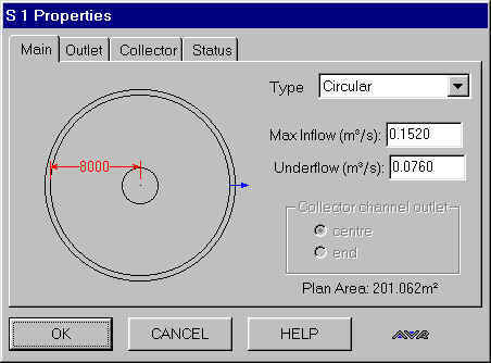
...with a pheripheral weir composed of V-notches.
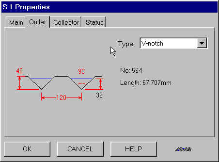
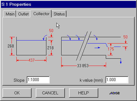
This example demonstrates a design feature of ARTS. ARTS automatically recalculates dependent parameters, in this case the overflow weir parameters are dependent on the inflow and the tank diameter. If you change either of these ARTS recalculates the parameter values for the outlet weir, thereby always providing you with an operable initial set of values.
WWTP
hydraulic profile computation![]()
The treatment system may incorporate any of the following hydraulic objects on the tool palette: activated sludge reactor, flume, pipe, biofilter, reservoir, detritor, flow divider, screen, primary and secondary clarifiers, weir, channel.
The flow can be split into multiple parallel streams using the flow-divider tool. The hydraulic effect of taking one stream out of operation for repair/maintenance purposes can be readily examined.
The system inflow range is defined by placing a flow graphic at the head of the system under consideration and editing the flow objects properties including Maximum flow, Minimum flow, Average flow wastewater temperature. Subsidiary inflows and outflows to and from points along the system are also permissible.
The TWLs, which define the hydraulic profile across the system, are computed with reference to a user-input datum level at the outlet node of the system.
In computing head loss across the system, ARTS automatically takes inlet and outlet head losses in the linking pipes into account, as well as the local losses at pipe junctions, where there is a change in diameter. In addition, you can edit the linking pipe property pages to include fittings such as bends and valves, etc.
The ARTS Hydraulic Profile menu includes an Auto Design command which can be used to generate an initial treatment system, whose elements are capable of transmitting the maximum flow. You can then be refine the design by the user by editing the property pages of the component elements of the system.